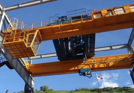
Overhead travelling crane is often called as bridge crane. This type of crane is most commonly used in workshops, warehouses, power plants and factories. Overhead travelling crane consists of hoist & trolley, girder, end carriages, runway rail, runway beam, electrical, panel, and control systems. If the systems use only one main girder they are called single girder overhead travelling cranes and if use two bridges they are called double girder overhead travelling cranes.
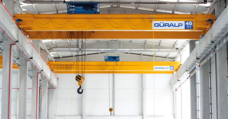
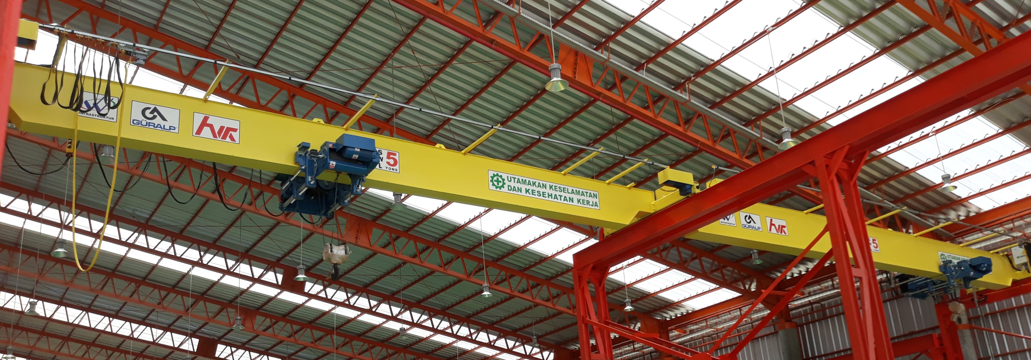
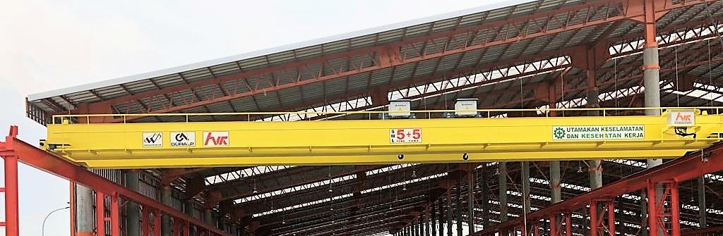
Single girder overhead travelling cranes are generally preferred for capacities up to 12 tons and span values below 30 meters. They are more economical as compared with double girder overhead travelling cranes in standard applications. The crane consists of a single girder supported on two end carriages. For maintenance, additional equipment such as ladder and platform is needed. Double girder overhead travelling cranes widely used to lift very heavy loads. With the facilities and support from our manpower, we able to produce up to 200 tons lifting capacity, and up to 50 meters span depending on the capacity.
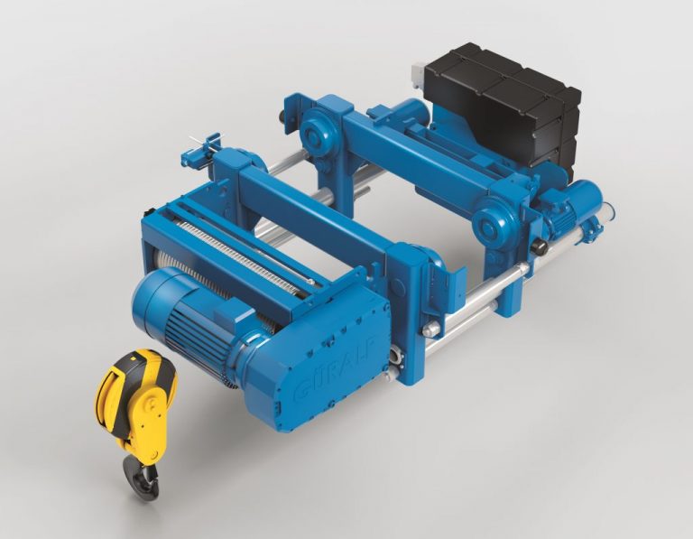
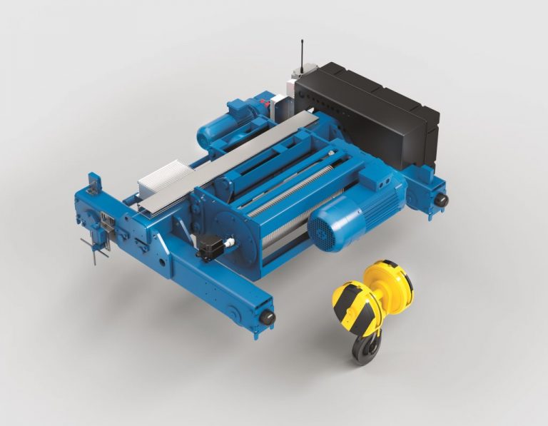
1. Hoist & Trolley.
In the single girder hoist (monorail hoist), the trolley wheels at the top of the hoist run on the bottom flange of the girder. It can be moved left and right along the girder or we called it crossing. Whereas in the double girder hoist, the trolley is paired with a rail at the top of the girder whose width is adjusted to the width of the flange on the trolley wheel. To drive the trolley, an electric motor that is adjusted to the maximum load, working-class and crane applications is used. There is a panel to control the work of the hoist.
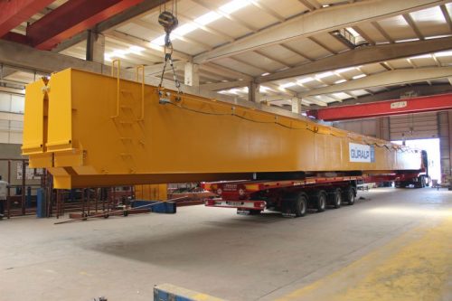
2. Girder.
Girder is usually made of steel plates formed into box girder with thickness and size adjusted to the maximum deflection and the desired load capacity. In some applications with a load capacity that is not too heavy and with a maximum span 12 meters we can use IWF or H Beam steel profile. In addition to holding the load on the hoist, the girder also functions as hoist trolley track. To facilitate maintenance access, a service/maintenance platform can be installed at one side of the double girder. In the single girder type, maintenance platforms can be installed at the end of the runway to facilitate maintenance access.
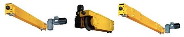
3. End Carriages.
To make the crane move forward or backward (travelling) then at both ends of the girder end carriages are installed, consisting of wheels, boxes, as well as motors and gearboxes. The wheel diameter of the end carriages adjusted to the capacity of the crane, the width of the span, the travelling speed and the working class. The parts of the girder and end carriages can be connected in a side joint (the end of the girder facing outwards with the outside side of the end carriages facing inward) or top joint (the bottom of the girder with the top of the end carriages).
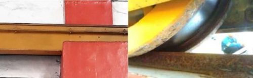
4. Runway Rail.
Crane rails installed above the runway beam with a width which adjusted to the flange on the end carriages wheels, it can be a flat bar, square bar or in some applications we can also use “A Rail” profile. For the runway beam, we can use IWF or H Beam profile steel material and usually above the console in a building column-mounted along with the long travel.
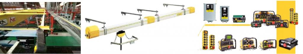
5. Electrical, Panel and Control.
For the electricity supply along the runway, we generally use a power conductor rail system that will distribute electric current through a trolley connector mounted on left or on right side of crane. Then to continue the electric current to the hoist, we used festoon / flat cable which is connected with push-button pendant control, fixed one or mobile pendant that can be pulled or moved by the operator along the girder. Bridge panel (crane control panel) completes the electrical to regulates and controls the crane system.
6. Additional Components :

© PT HWK 2019
Silakan hubungi kami / WhatsApp us
